Introduction
The success of a DC to AC power inverter installation depends mainly on the methods and materials used for the installation. Low DC input voltage inverters (12 or 24 Volts DC) require high DC input currents. For example, to provide a service of 15 Amperes at 120 Volts AC (1800 Watts) from a 12 Volt battery, the DC current will approach 180 Amperes! How can we supply such a high current to the inverter safely and efficiently? This article will guide you through a successful power inverter installation.
We are beginning with the assumption that the main three system components - inverter, battery, and alternator - have all been chosen. While installing and wiring these components we will follow the standards and recommended practices described by the:
- National Fire and Protection Association (NFPA)
- National Electrical Code Handbook- NEC 96
- Society of Automotive Engineers (SAE)
- SAE Handbook Volumes 1-4
Inverter Installations
Using the Existing Alternator and Battery, what are the system limits for a practical inverter installation using the existing under-the-hood alternator and battery? A majority of utility vehicles have a 100 to 130 Ampere alternator together with one or two group-27 batteries. Although the alternator cannot keep up with a continuous full-load current demand of more than 50 Amperes, it can provide enough for short term power use. In many cases the use of electrical power to do work is intermittent (using tools off and on for short periods of time). In these cases the alternator is able to "keep up" with power use and recharge the battery. There have been many successful installations of a 2300 Watt inverter in such trucks.
Other successful, smaller installations consist of an 1100 Watt inverter system in a smaller utility van or truck:
- Alternator rated at least 85 Amperes.
- A deep-cycle battery, Group 27 or larger in size.
- Wire from the inverter to the battery is 2 gauge at up to 15 feet (one way distance)
Where larger inverters than these are used, or where more continuous power is required, it is recommended that a battery pack be installed as close as possible to the inverter and that the alternator system be upgraded.
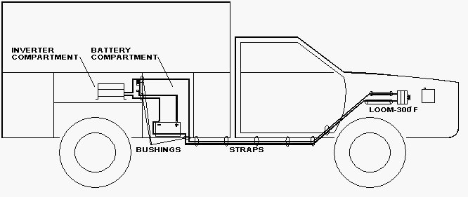
Inverter Installation (refer to Figure 1) Compartment:
The power inverter is an electronic device and is therefore somewhat sensitive to external factors. Temperature extremes, moisture, and air-borne contamination which will be drawn into the housing whenever the cooling fan runs - can shorten life. Some areas to avoid mounting the inverter are under-the-hood, on the floor over the exhaust system, or in sealed areas where moisture could condense. The ideal inverter compartment should be a clean, dry, cool compartment with some ventilation. Note that the inverter cannot share an area where combustible fuel vapors exist because switching components could cause ignition. Corrosive battery fumes should also not be present.
Mounting the Inverter:
Bolt the inverter securely on either a platform or bulkhead. Leave at least one inch of space all around the cabinet and especially above the cabinet for warm air to move out. The inverter face and the side where large DC cables enter should be visible and accessible for ease of wiring, ground fault interrupter testing and status lights viewing.
Fuse Holder Installation:
All wiring from a battery must be protected with the proper size fuses. All fuses and fuse holders should be located within 18 inches of the battery (Figures 2 through 5). Additional fuse holders may be required if the inverter is connected to the engine battery instead of the alternator, or if the under-the-hood wiring is upgraded. The auxiliary battery fuse protects the wires to the inverter and the wires to the alternator. Another fuse holder must be mounted at the engine battery if a direct connection is made. These auxiliary battery fuse holders must not be installed in an airtight battery compartment because of the explosion hazard mentioned earlier. Mount the fuse holders in a convenient place within 18 inches of the battery and label the fuse rating adjacent to its holder. Do not place the fuses into the fuse holders until all wiring has been completed.
Battery Installation Compartment:
The battery area must be vapor-tight to the interior of the vehicle and vented directly to the exterior. It must be assumed that hydrogen gas is continuously evolving from the battery. This gas is lighter than air and will quickly escape through openings at the top of the compartment. Openings at the bottom of the compartment will let in replacement fresh air. Install several vent-plugs within one inch of both top and bottom of this area. Note that the battery cannot share an airtight area containing spark-producing equipment, such as the inverter or fuses which could ignite the hydrogen gas.
Mounting the Battery:
Mount the Battery using hold-downs, trays, or boxes. Secure to a level, clean surface. Battery boxes must be of the vented type to allow for the escape of gases. Allow space around the battery and especially above the battery for ventilation, inspection, and maintenance. The battery should not move more than 1 inch in any direction, even if upside-down. A framework of angle iron, together with a protective cover, can be fabricated for large systems.
DC Wiring:
1. Use SGX cable
- SGX cross-linked polyurethane cable complies with SAE J-1127 and vehicle manufacturer requirements.
- SGX insulation meets the high temperature requirements (125°C.) of J-1127.
- Refer to AN102 to determine the proper gauge cable and fusing for your application.
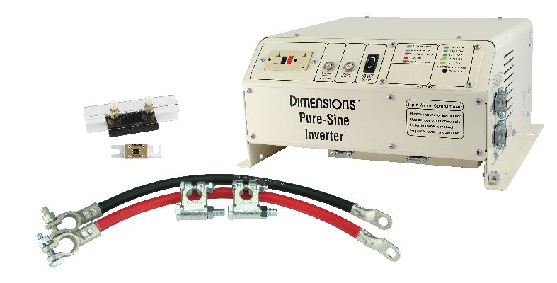
- Sensata can supply complete cable assemblies with fuse and fuse holders.
2. Cabling diagrams
- Figure 2 and 3 are diagrams for a smaller inverter (1000 Watt or less) where no auxiliary battery is being installed.
- Figure 4 is a diagram for a larger inverter (1000 Watt or more) where one or more auxiliary batteries are being installed.
- Figure 5 is a diagram for a larger inverter where one or more auxiliary batteries are being installed and cabling is to the OEM battery.
3. Routing the cables
Refer to Figure 1. Run both charging cables directly to the alternator. Do not use the vehicle chassis as a conductor.
- When going through a partition, use a protective rubber grommet to prevent abrasion of the insulation. Seal the excess opening with caulk to prevent fume entry.
- When routing under the vehicle, secure the cables with clamps every 18 inches, to prevent a snag. Keep the cables away from the drive shaft, exhaust system, and fuel line.
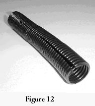
- When routing in the engine compartment, use high temperature (300°C.) loom and route the coolest way possible.
AC Wiring:
AC wiring must be stranded copper conductors for vibration resistance and must also be protected by a conduit. Route closely to the frame. Use electrical tape over the wire nuts at the terminations because they can be loosened by vibration.
1. Use "Boat and Truck Cable" for up to 10 AWGUL listed, meets DOT specifications
- Stranded copper
- 16 to 10 AWG
- Nonmetallic
2. Use Type NM-B cable or Individual Building Wire conductors above 10AWG
- UL listed
- Stranded copper
- Nonmetallic
3. Use conduit
- Metallic: use rigid Electrical Metallic Tubing
- Nonmetallic: use rigid PVC
4. Use junction and outlet boxes that match the selected conduit system
5. Bonding Connect a # 8 gauge stranded copper wire from the bonding lug on the inverter chassis to the vehicle chassis. The connections must be tight against bare metal. Use star washers to penetrate paint and corrosion. This safety requirement also reduces radio interference (the Dimensions Inverter is UL listed, its DC input connections are isolated from the chassis).
Figure 1 Cable Routing for Inverter Installation:
Guidelines for Fusing between Inverter, Batteries, and Alternator
All fuses within 18" of battery - Ref: 1996 NEC article 551-10 (e)-(4)
Figure 2 Inverter Cabling Diagram (1000 watts or less), no auxilliary battery(s), OEM alternator:
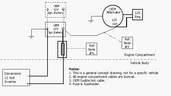
Figure 3 Inverter Cabling Diagram (1000 watts or less), no auxilliary battery(s), upgraded high output alternator:
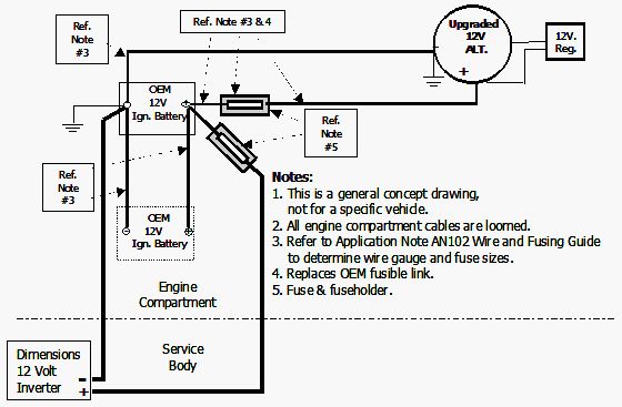
Figure 4 Inverter Cabling Diagram (1000 watts or less), with auxiliary battery(s) (preferred method)
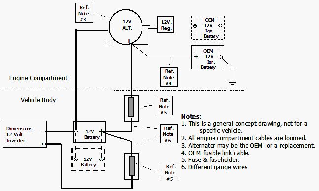
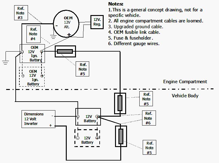
Figure 5 Inverter Cabling Diagram (1000 watts or less), with auxiliary battery(s)
DC WIRING
Terminating the cable:
Cut the cable using a shear-type cable cutting tool (figure 6). Strip the insulation from the cable using a rotary type cable stripper tool (figure 7).

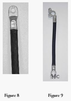
Battery connections can be made with ring (figure 8) or clamp (figure 9) terminals. Make alternator connections with ring terminals. Use 5/16" ring terminals for the fuseholder connections.
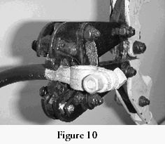
Crimp terminals using a long-handle multi-die crimping tool (figure 10).
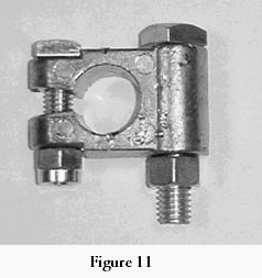
When two cables must be connected to a single battery post, use a post clamp type terminal (figure 11).
All engine compartment wiring and cabling must be in high temperture (300 degrees C) loom (figure 12).